![]()
| Open the Isolde Controls file in the Isolde Control System directory. Choose the Easy Eqp. Access tool and enter gps.wg475 in the Equipment Name dialog box. Press the Attach control Panel button. The Wire grid GPS.WG475 will appear: |
| Choose the atom you want to have with the Mass Control tool GPS.MAG70 Mass Control. Let us suppose that you have chosen the 132Xe (xenon 132). | |
| On the GPS.WG475, you will be able to see the beam profile of the species you have chosen with the Mass control tool, 132Xe in our example. | |
| To improve the aspect of your curve you can play with the Sensitivity button. | |
| To understand the function of the Slit and Grid buttons, see the sketches and explanations below: |
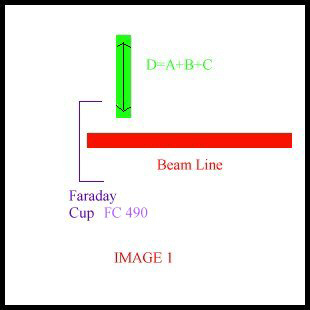
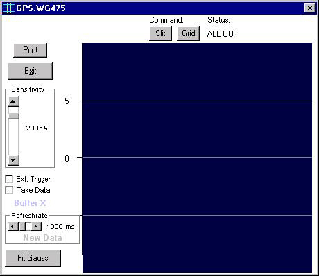
IMAGE 1 represents the way we can draw the beam profiles. The beams corresponding to the different isotopes come following the beam line, are collected and measured in the Faraday cup.
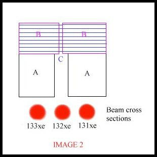
IMAGE 2 represents an apparatus used on the beam line (corresponds to the section called D=A+B+C on IMAGE 1) to select the beam we want to have in the Faraday Cup. The section called A represents a slit that lets about 90% to 100% of the central beam (the isotope we have chosen) pass through it, the section called B is a finer slit which lets only about 10% to 25% of the central beam through and the section called C represents the grid. The set A+B+C is a rigid piece that can be moved vertically into the beam line.
| Press the Grid button (places the section B+C into the beam) or the Slit button (places the section A into the beam). If you choose the Out button, the set A+B+C will be taken away from the beam line and all beams represented on IMAGE 2 will pass through. |
| Back to top |
![]()